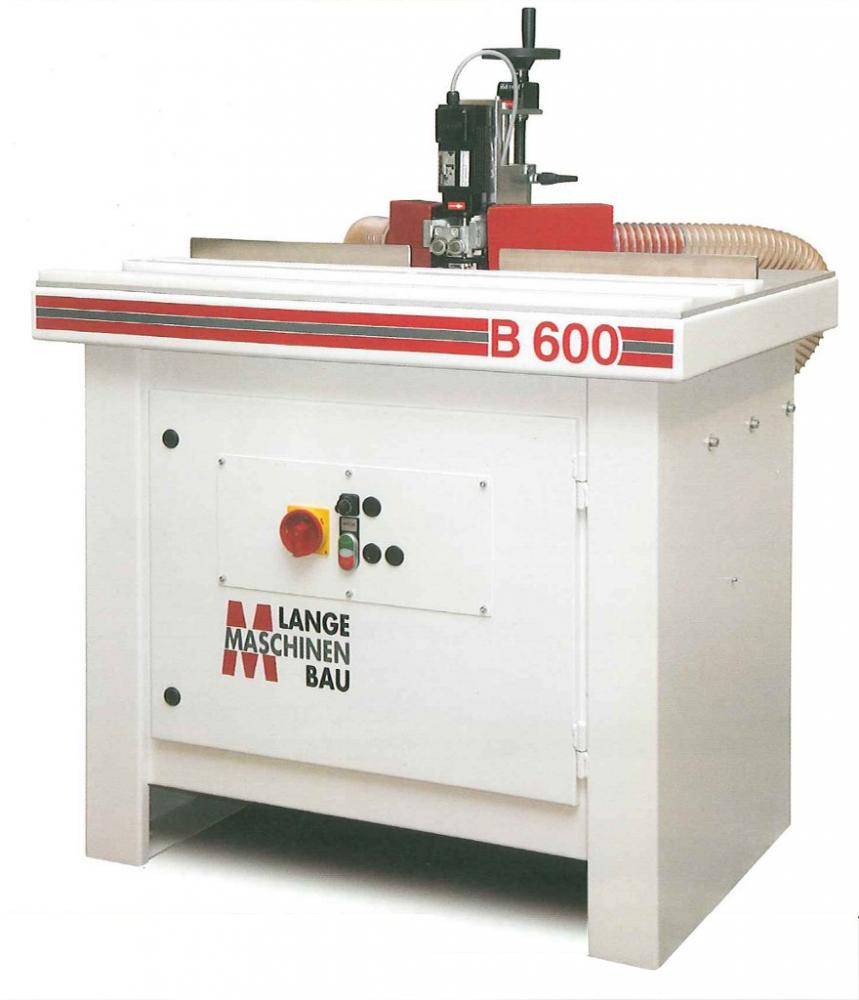
Bruska na hrany
Záznam uvidíte za
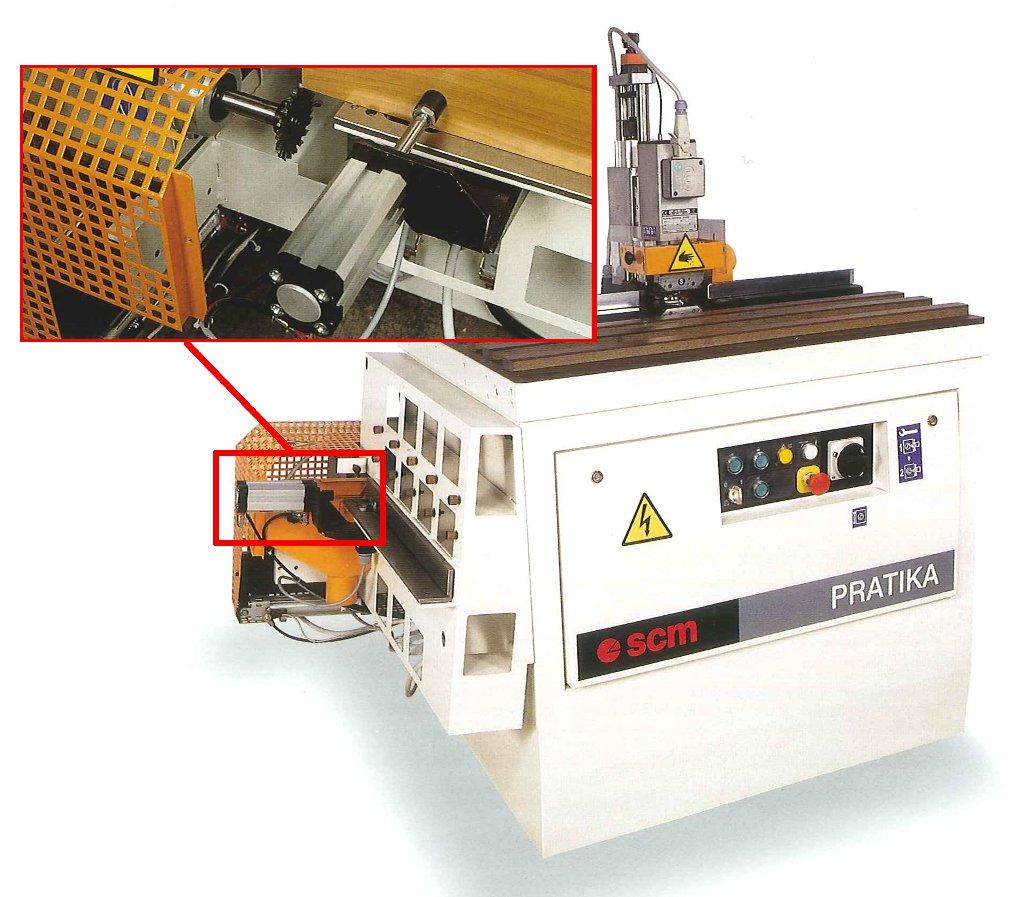
       Small stationary machines and portable handmachines for the post-processing of glued edgeband. Edgeband are glued onto the panel edge with overlappings in the length and in the height. The lengthwise overlap is removed with the help of a trimming saw on an edgebander or on another post-processing machine. The upper and lower overlap is trimed with the help of milling aggregates on edgebanders. Behind the trimming process are usually working stations for chamfering or radius milling. Small edgebanders and edgebanders for shaped workpieces with manual feeder do not have these Flush/radius/chamfer milling units. In such cases the milling process is done on the edge trimming machine. Structure and Working ProcessA milling aggregate, which is attached to a steel pedestal, consists of two motors with axes lying in a vertical position. So it becomes possible to process curved workpieces. Depending on whether the edgeband shall be flush milled or chamfered or radius milled the motors will be equipped with a fitting tool. The motors are floating. Through a special device the two motors are held at a certain distance to each other, so that the workpiece will not be scratched on its way towards the milling tools. At the workpiece approaches the cutter heads of the two impulse devices which are vertically connected to the motors are touching the workpiece on the surface. By hand the workpiece is driven through the milling aggregate. If curved workpieces are processed they will be guided through pressure on a horizontal turning disk. Because of the overlap of the lipping the workpiece needs to be mounted on a support. If straight pieces are processed a removeable fence is mounted for guidance. Little plastic stripes are mounted to bridge the gap which is needed for the overlap lippings on curved pieces. Options
HistoryEdge trimming machines of former times were serving different purposes. After the application of the solid wood lippings workpiece had to be trimmed to the right measure. In principle these machines worked like surface planers. The side of the workpiece, that had to be trimmed, was put downwards on a machine table which was adjustable in the height. A conveyor belt and inclined rollers as a counterpressure guided the workpiece over a planer head at the end of the table. The height adjustment of the infeed table determined the depth of the cut. | viz také Naposledy zobrazené |
Obrázky